Home / Model Expert Homepage / Model Expert Help / Analyzing your Model / Checking UML Sequence Diagrams
Import an MDG to create a Reference Model
Importing and exporting Reference Models
Editing RM Connector type properties
Stereotypes inheriting from other Element Types
Customizing Reference Model Properties
Customizing Reference Model Element Properties
Table of contents
Checking UML Sequence Diagrams
Table of contents
With Model Expert you can validate UML Sequence diagrams to check for some common errors:
- Lifelines not being instances of EA types
- Messages between lifelines not calling methods of the target
Note: Sequence diagrams are checked against a fixed set of rules, and do not use a reference model.
Example
| Step | Description | See Also |
|---|---|---|
| Find the package ‘Example 2 – Sequence diagrams’, and open the ‘Components’ diagram: | 
These are some simple components, with some simple operations. |
|
| Find the sequence diagram ‘Diagram #1’. | 
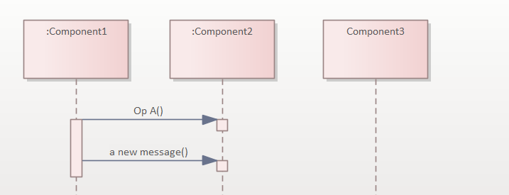
Note that Component 3 is not an instance of the component, it’s the component element itself – a deliberate mistake. If you switch on the diagram setting ‘Show Namespace’ then EA makes it more obvious that you’ve made a mistake..) |
|
Now create some messages between the components
|
This is the best way to avoid mistakes, but it only works if you know the EA trick of choosing valid operations from the drop-down. But EA will let you make a message using anything: | |
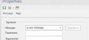
| Now create another message, but this time just type in a new name for the message:
|
This message doesn’t exist as an operation on the target component, so is probably an error.
The resulting sequence diagram now has two errors:
|
|
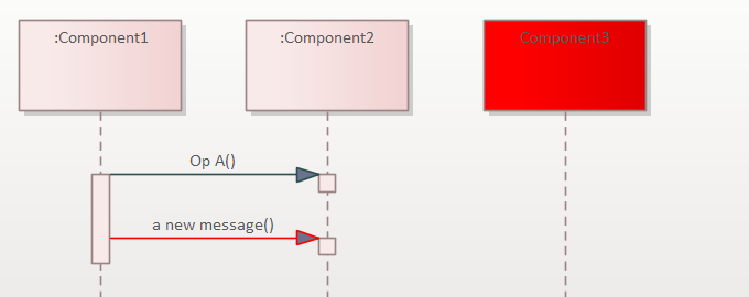
| Right-click on the diagram, and choose Specialize/Model Expert/Check sequence diagram | This produces a list of the errors in the diagram:
…and will add colors to the diagram, to show where the errors are:
|
|
| You can now see where to correct the errors in the diagram, using standard EA functions. |


